1. Concept of Roll Forging
2. Introduction to Roll Forging Technology
3. Forging Classification
4. Characteristics of Deformation
5. Basic Principles
6. Key Points in Mould Design
7. Types of Equipment
8. Applicated Industry
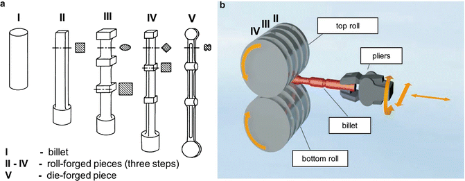
Concept of Roll Forging
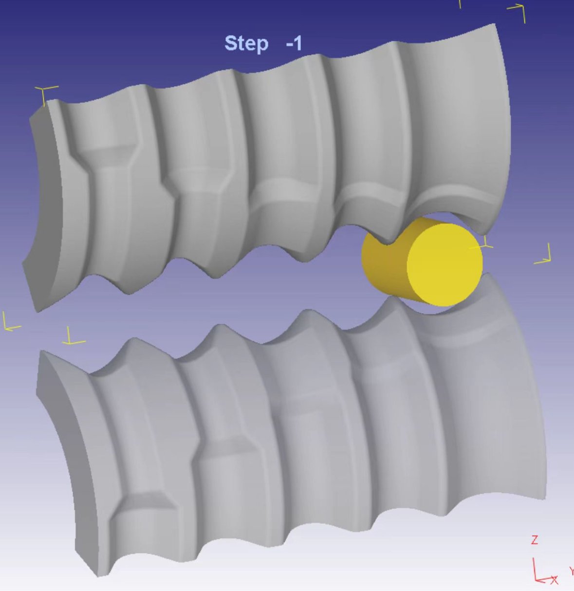
Forge rolling, also known as rotary forging or reducer rolling, is an advanced longitudinal rolling technique utilized to diminish the cross-sectional area of heated materials, such as bars or billets, by guiding them through opposing rotating rolls equipped with one or more shaped grooves. This process yields workpieces with variable cross sections along their length, achieved through the strategic use of interchangeable roll segments. A series of these matched rolling segment pairs are orchestrated in a meticulously planned forming sequence, with each stage referred to as a “pass.” The adaptability of the roll segments permits varied material distribution across different passes, with the final workpiece shape being determined by the inverse contours of the roll segments. Forge rolling is predominantly employed in the initial shaping phase, or preforming, within a comprehensive forging sequence for elongated components.
Introduction to Roll Forging Technology
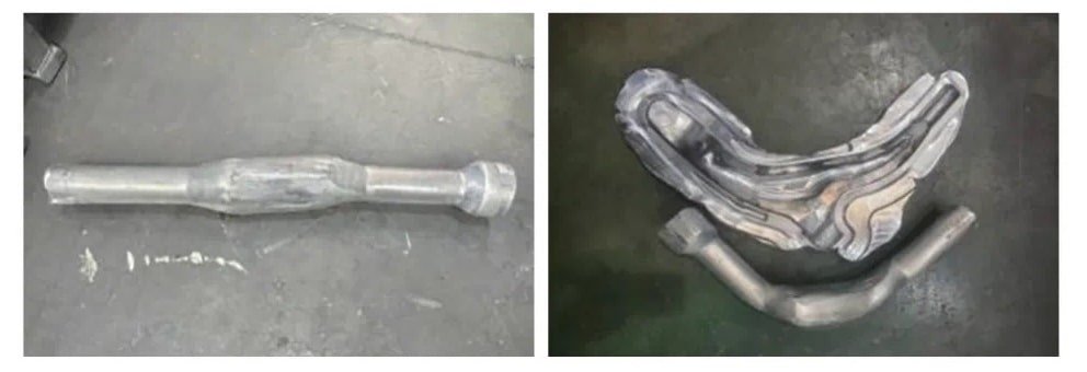
Roll forging boasts superior technical and economic advantages over die forging, characterized by lower required workloads, higher production efficiency, reduced material consumption, superior quality, and better working conditions. It serves as an excellent alternative solution to traditional forging methods like the air hammer. Roll forging is suitable for producing a wide array of items, including automotive connecting rods, twist drill bits, riggings, wrenches, spikes, hoes, picks, and components like turbine blades and excavator bucket teeth, arm-type parts, auto shafts, front axles, crankshafts, plow blades, sickles. Leveraging the principles of rolling deformation, roll forging gradually shapes the workpiece. Compared to conventional die forging, it offers the benefits of simpler equipment structure, stable production, minimal vibration and noise, ease of automation, and high production efficiency.

Forging Classification
Roll forging is categorized into two types: billet roll forging and shape roll forging. Billet roll forging prepares the blank in the required shape and size for die forging, while shape roll forging can directly produce forgings that meet specific shape and size requirements.
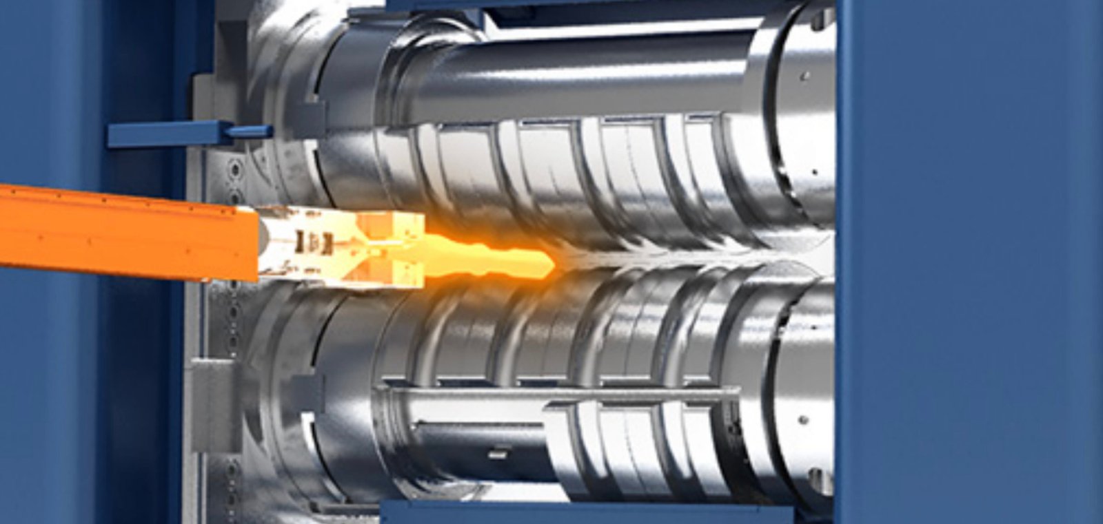
The essence of roll forging deformation is the rolling extension of the workpiece, where part of the cross-section decreases in size while its surface area increases. When significant cross-sectional deformation is required, multiple rolling passes are needed. The process design primarily involves determining the appropriate amount of compression, widening, and elongation for each step of roll forging. These factors depend on the roll diameter, the shape and size of the die, the temperature of the blank, and deformation conditions such as cooling and lubrication. One end of the blank is clamped, deformed under the pressure of the first die in a sector mold (initial forming), and then removed; it is then fed into the next die’s open space without a mold, pressed again (preforming), and removed. Depending on the deformation requirements, multiple rolling passes gradually shape the workpiece until the desired shape is achieved (final forming).
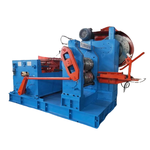
This is the most common method of reverse roll forging. When the feed direction is along the rotation direction of the rolls, it is called forward roll forging, and the clamp is immediately released after the workpiece is gripped. The most commonly used roll forging machines are double-supported roll forging machines with frames on both sides, offering high rigidity and capable of producing high-precision forgings. These machines come in various specifications with roll diameters ranging from 250 to 1250 millimeters and corresponding roll forging forces from 400 to 4000 kilonewtons. Some double-supported roll forging machines have an extended roll shaft at one end, combining cantilever and double-supported designs. This allows for both longitudinal roll forging and lateral widening at the cantilever end. In mass roll forging production, robotic arms are widely used to transport workpieces, automating the production process, increasing productivity, and reducing labor intensity.
Characteristics of Deformation
Roll forging is a forming process where material undergoes deformation under the action of a pair of counter-rotating dies to produce the desired forging or billet. The principle of roll forging deformation is illustrated in Figure 1. Roll forging involves complex three-dimensional deformation. Most of the deforming material flows along the length direction, increasing the length of the billet, while a smaller portion flows laterally, increasing the width of the billet. During the roll forging process, the cross-sectional area of the billet continuously decreases. Roll forging is suitable for elongating shaft-like parts, rolling slabs into plates, and distributing material along the length direction of the deformation process.
Basic Principles
(1) The initiation of roll forging begins only when the billet is bitten by the roll forging die. In practice, there are two types of bite: natural bite at the ends and middle bite, as shown in Figure 2. In the case of natural bite at the ends, the friction between the die and the billet is the driving force for the bite, while the component of pressure “p” on the billet acts as the resistance. The angle “α” in the diagram is referred to as the bite angle. Increasing the friction coefficient and reducing the bite angle facilitate the biting process. The friction coefficient can be increased by roughening the die surface, and the bite angle can be reduced by decreasing the absolute reduction amount. Middle bite occurs when the protruding parts of the roll forging die press directly into the billet, forcibly pulling the billet into the deformation zone, unaffected by friction, allowing for a larger bite angle. Middle bite is necessary to reduce the number of roll forging passes and increase the reduction per pass. For a natural bite at the ends, the bite angle should not exceed 25º, while for a middle bite, it can reach 32º–37º.
(2) During the forward slip in roll forging, the volume of material flowing into the deformation zone is equal to that flowing out at any given moment, but the height of the deformation zone changes, so the material’s movement speed along the roll forging direction also varies. At the exit of the deformation zone, the material’s movement speed exceeds the linear speed of the forging roll. This phenomenon is known as forward slip. Since the length of the forged piece is determined by the exit speed, calculating the forward slip is significant. The Fink formula for calculating forward slip is:

where S is the forward slip value, R is the radius of the roll forging die, α is the bite angle, β is the friction angle, and h is the height at the exit of the deformation zone.
The Fink formula, derived under the assumption of neglecting width, is an approximate formula for calculating simple deformations. For longitudinal roll forging with constrained cross-sections by the die, the forward slip value is smaller than that of simple roll forging.
(3) The lateral flow of material during roll forging results in widening. Factors influencing widening primarily include the absolute reduction amount, roll forging die diameter, original width of the billet, and friction coefficient. An increase in the absolute reduction amount, die diameter, friction coefficient, and a decrease in the original billet width all contribute to greater widening. Although there are many theoretical formulas for calculating widening, they are proposed under specific conditions and may have significant errors when applied to complex die roll forging. Currently, the equivalent rectangle method is used, which involves converting the die shape into a rectangle and using the formula for flat rolling, followed by adjustments
Key Points in Mould Design
- For billet roll forging, the billet should be selected according to the requirements for calculating the blank diagram, and the number of roll forging passes should be determined based on the maximum degree of deformation. The groove system should be chosen, and the deformation amount for each pass should be reasonably distributed. The billet section size for each pass should be calculated based on the deformation pattern, ensuring that the deformations in each pass are compatible, with the rational selection of the groove series being key. The groove series scheme is shown in Figure 4, and Table 2 lists the commonly used groove series. In selecting the groove series, in addition to reasonably distributing the deformation amount, the stability during roll forging must also be considered. Attention should be paid to the fit between the groove shape and the billet, and the limitations imposed by stability conditions on increasing the deformation amount should also be considered.
- For the forming roll forging groove, in addition to considering the key points of the billet roll forging design, the requirements for formability and dimensional accuracy must also be taken into account. As shown in Figure 3, the backsliding area occupies most of the deformation zone during roll forging, making the back wall of the groove easier to form than the front wall. By changing the direction of roll forging, both the front and back walls can be placed in an easily formable area, ensuring good filling of the groove. Accurate calculation of the forward slip value can ensure dimensional accuracy in the length direction. In addition to theoretical calculations, it is also important to refer to examples of existing measured data.
Types of Equipment
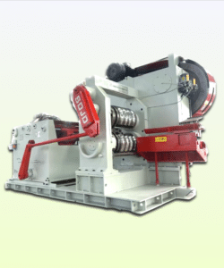
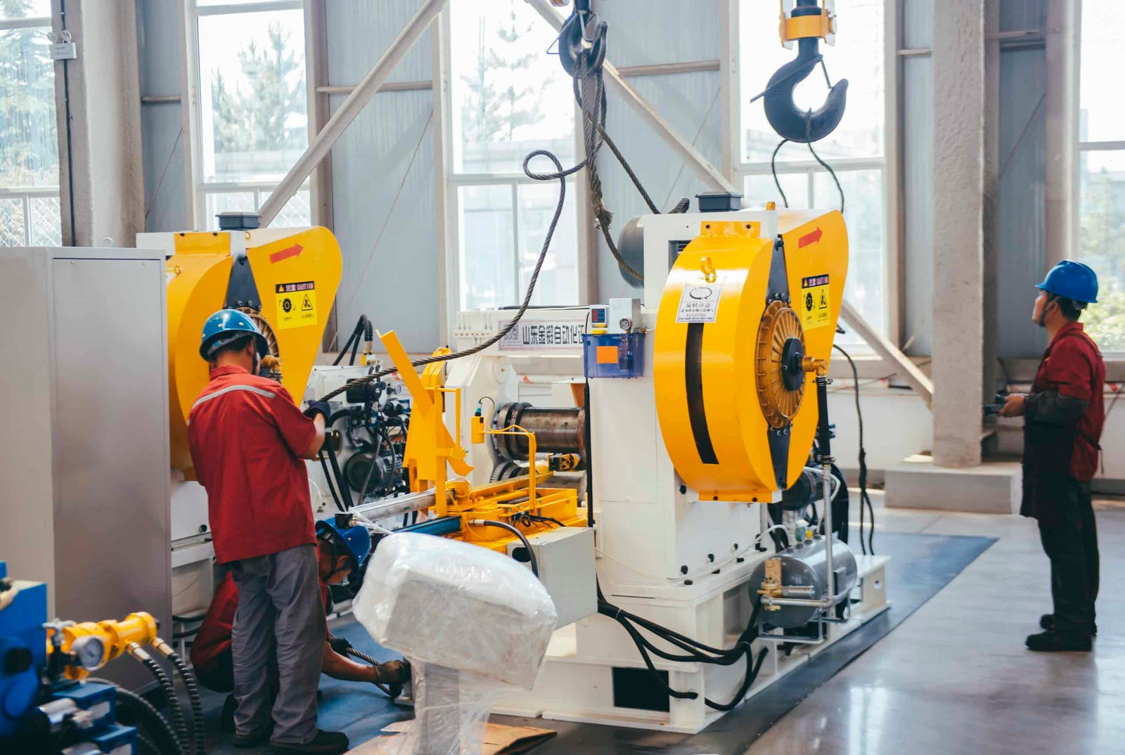
Nowadays most commonly applied roll forging machines can be categorized into three types: double-supported, cantilever, and composite. The early split-frame roll forging machines, similar to rolling mills, are now rarely seen. Automatic roll forging machines are commonly found on roll forging billet production lines. These machines connect double-supported roll forging machines with automated robotic arms, achieving full automation across multiple forging passes
Applicated Industry
One application area is precision roll forging technology, including cold precision rolling techniques. This has promising prospects for the precision forming of sheet metal parts, showing advantages in blade forming and variable cross-section steel leaf springs. The second area involves achieving volume distribution and preforming in the production of long shaft forgings, reducing the load required for final forming. This leads to the creation of precision rolling and forging composite production lines, allowing for the mass production of complex forgings with minimal investment. The precision rolling and forging production line for truck front axles is a successful example. The investment for this type of production line is only 1/5 to 1/8 of that for traditional press lines with capacities of ten thousand tons, yet it offers comparable product quality and production capacity. The development of roll forging forming technology will drive technical progress in the world’s forging industry in these two areas.

