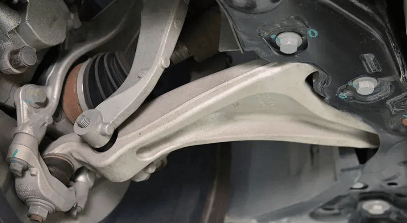
The control arm, also known as the lower wishbone, is installed in the front suspension MacPherson structure of a vehicle. Its function is to closely connect the vehicle body with the wheel hub and support the vehicle’s weight during driving or stationary conditions. Currently, common types of control arms include forged steel, cast steel, stamped and welded steel parts, and forged aluminum alloy.
Among them, aluminum alloy control arms are particularly valued for their lightweight nature, which reduces the overall sprung mass of the vehicle. This results in significantly improved handling performance. In the case of new energy vehicles, the reduced weight also helps lower energy consumption and increase driving range.
With proper process design and locked-in forging sequences, aluminum alloy components can achieve high and stable strength, excellent elongation, and satisfy the impact loads and road condition requirements during driving. Moreover, aluminum alloys exhibit better corrosion resistance than steel, making forged aluminum control arms an increasingly attractive choice for mainstream car manufacturers and emerging EV brands.
As a result, the selection of a stable and reliable forging process becomes especially important. This article focuses on the forming process plan for an aluminum alloy control arm.

Product Structural Analysis
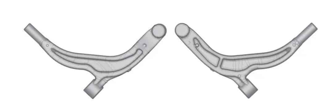
As shown in Figure 1, this specific aluminum forged control arm has a theoretical weight of 4.1 kg. The raw material is Al6082, with a T6 heat treatment requirement (solution treatment + artificial aging). The finished product must undergo 100% fluorescent penetrant inspection (FPI) to ensure no folds, cracks, porosity, dents, or underfills on the surface. The final surface treatment is shot blasting.
There are typically two billet preparation methods for forging aluminum alloy control arms: open-die forging and roll forging. Open-die forging involves high labor intensity, low efficiency, poor consistency, and is not suitable for automated production. As automotive production accelerates, open-die billet preparation is becoming increasingly unsuitable.
This article focuses on the application of roll forging in the billet preparation for this type of aluminum alloy control arm.
Forming Process and Material Selection
Based on the existing equipment in the workshop, the initial process flow is defined as:
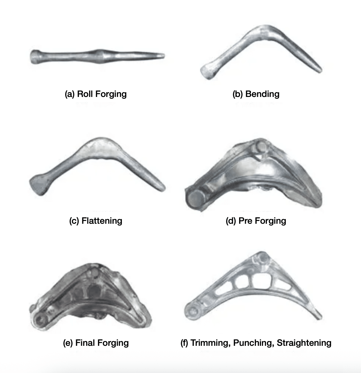
Sawing → Heating → Roll forging → Bending → Flattening → Pre-forging → Reheating → Final forging → Trimming → Solution treatment → Aging → 100% FPI → Shot blasting
As shown in Figure 2, the product is divided into segments perpendicular to its length. Using 3D software, the cross-sectional area of each segment and local volume are measured and analyzed. Combined with finite element simulations, this guides the material selection.
The selected billet size is φ82mm × 420mm aluminum alloy bar, with a theoretical material utilization rate of 67.71%.

Design Development and Analysis
Product and Die Design
- Based on the 3D model provided by the customer, machining allowances and draft angles are added in areas requiring subsequent processing. A typical allowance is 1.5–2.5mm per side, and the draft angle is generally between 3° and 7°.
Related forging dies are shown in Figure 3. The dies involved in the production of this product include: roll forging dies, bending dies, pre-forging dies, final forging dies, and trimming dies. Key considerations in the design of these dies are as follows:
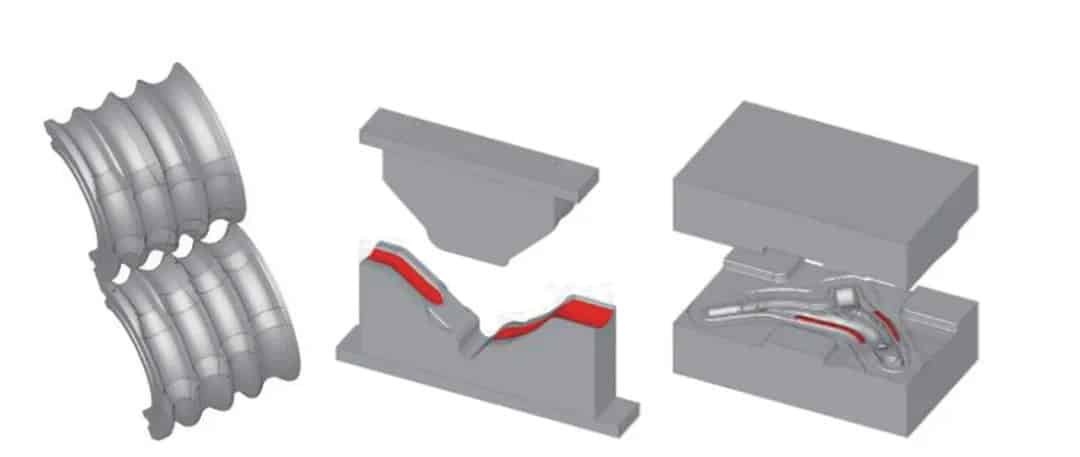
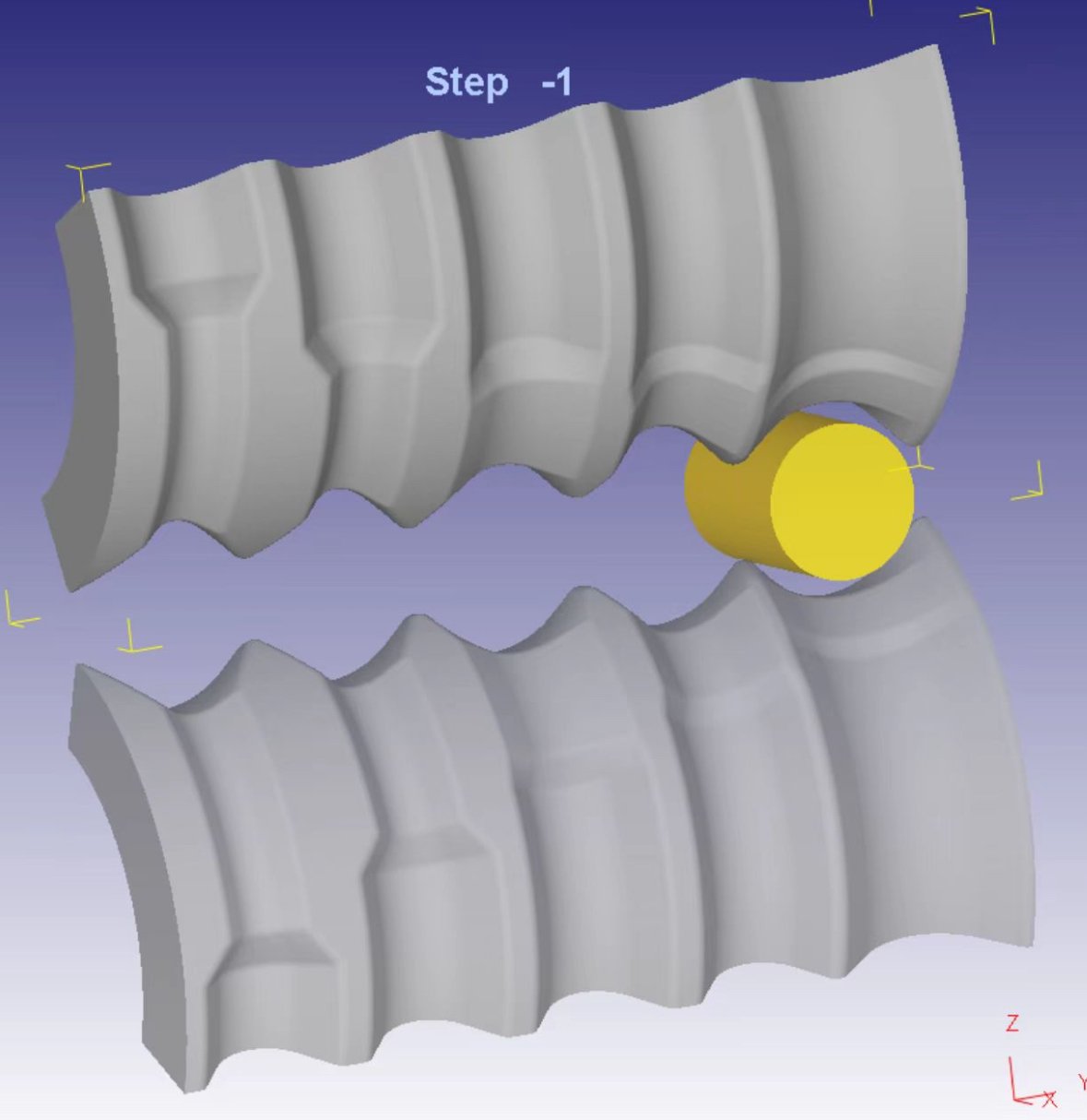
- Roll Forging Die: Based on calculated results, φ82mm raw material is selected. The minimum diameter after roll forging is φ52mm. To avoid excessive deformation or visible extrusion marks, four passes are used.
- Bending Die: The forming area should be machined into an arc shape to ensure consistent placement and bending of the billet.
- Pre-forging Die: In areas where material flow may be unstable, flow-blocking features are added to ensure sufficient cavity fill.
- Other Design Notes: Refer to forging design handbooks for further techniques and recommendations.
Finite Element Analysis (FEA)
- Roll Forging Analysis: No significant burrs or sharp edges observed (Figure 4).
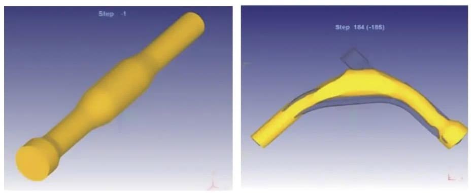
2. Bending & Flattening Analysis: Final shape closely matches the target product (Figure 4).
3. Pre-Forging Analysis (Figure 5): Theoretical forming force is 1980 tons. Material fill and flash distribution are acceptable. No major defects in the forming area.

4. Final Forging Analysis (Figure 6): Theoretical forming force is 3030 tons, whereas current press capacity is 2000 tons. Material fill and flash are satisfactory, and no significant forming defects are found.

5. Based on theoretical analysis, the tooling design is feasible and ready for fabrication.
Die Manufacturing
Given the tight development schedule and the number of required dies, manufacturing was outsourced to Xuancheng Tengyue Mold Co., Ltd. to ensure project timeline. The finished dies are shown in Figure 7.

Die Trials and Sample Production
- Two heating cycles were performed using a chain-type mesh belt furnace. Heating temperature was set at 510°C.
- Roll Forging Trial: The shape and size of the billets closely match the design. Due to large deformation, billet straightness is not ideal (Figure 8), but does not affect the next step.
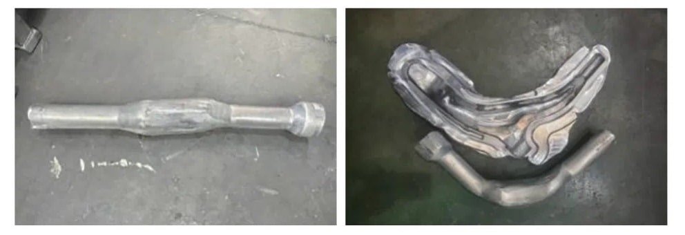
3. Bending & Flattening Trial: Result is consistent with the FEA simulation (Figure 8).
4. Pre-Forging & Final Forging Trials:
- Figure 9 shows actual pre-forged parts. The 2000-ton press was used at 90% capacity. Results are close to simulation, but thickness exceeds the design by 1–1.5mm. Since final forging follows, no adjustments were made.

- Figure 9 shows the final forged parts. Forging energy matched pre-forging. Thickness exceeds design by 1.5–2.2mm but is acceptable upon review of product drawings.
- Based on the comparison of simulations and actual trials, it is recommended to use a 2500–4000 ton press. If only 1600–2500 ton press is available, an additional trimming and forging operation may be needed to meet dimensional tolerances.
5. 100% Fluorescent Penetrant Inspection (FPI) and Shot Blasting (Figure 10): Per customer requirement and functional use of the part, all heat-treated products undergo 100% FPI to ensure no visible forging defects. For shot blasting, stainless steel or a mixed media of stainless steel and aluminum alloy shot is recommended.

Conclusion
During the product development process, finite element analysis (FEA) significantly shortened development time and reduced the number of die trial iterations. This helped to ensure that the development cycle of the product was both controlled and efficient.

